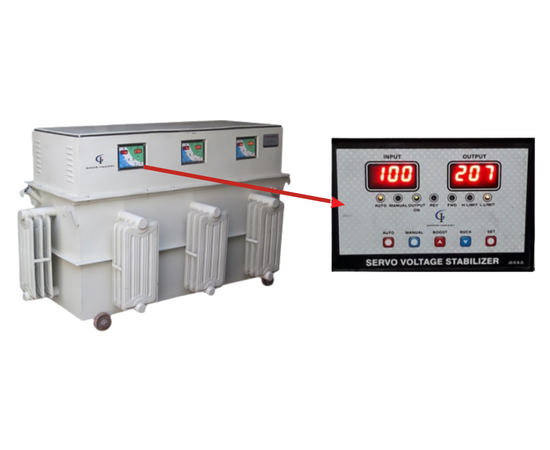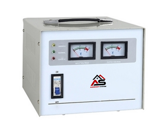
The importance of the use of servo voltage stabilizer (single and three phase) with sensitive electronic & electric equipment is well know. No one likes to risk the life of costlier appliances, CNC machines, electric equipments, motors lab equipment, Medical equipment etc. By connecting Ac voltage which is not stabilize and dips at the point of time and at other point of time rises to very high value. Aadishakti servo voltage stabilizer have been designed to give a constant output voltage for SYS well as three phase applications with stability + 1% the efficiency has been Maintained as high as 98% or more.
Output voltage stability of servo voltage stabilizer allows the optimum drawing of the current by load and as such no extra electrical power is consumed at low as well as high voltage there fore use of the servo voltage stabilizer saves power and reduces MDI. The micro processor control makes operation flaw less


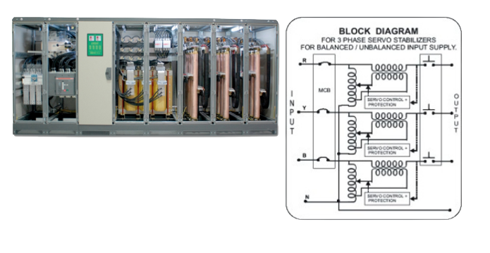
This control circuit continuously monitors the output voltage and monitors of any errors in output side. Any changes in output side is immediately corrected by the switching on the servo motors attaches to veracious increase and decreases to voltage to primary of buck / boost transformers. The Buck/Boost transformers adds or subtracts the voltage to mains so that the output voltage remains within the require limit.

This Basically consist of three single phase units of one third capacity each, connected In “STAR”. The Output voltage on all three Phases are balanced eve if the input voltage and the loads connected on the three phase are entirely different (Unbalanced).
This is combination of three variacs, along with three servo Motors, three buck and boost transformer and three solid-state control circuits.

| TECHNICAL SPECIFICATION | |
|---|---|
| Standard | Confirms to Least IS-9815 & ISO 9001-2000 Standards |
| Rating | 1KVA to 100 KVA Single Phase 3KVA to 3000 KVA Three Phase |
| Input Voltage Range | 1 Phase 90V, 120V-140V-160V-180V to 270V and 300V 3 Phase 150V-220V, 250-270V-300V-320V360V to 460V and 500V |
| Output Voltage Range | 1 Phase 220/230/240+/-1% 3 Phase 380/400/215+/-1% |
| Output Waveform | No Distortion |
| Response Time | 10 m.sec |
| Correction speed | 10-35V/sec |
| Correction Method | Stepless correction using Variac |
| Control Circuit | Fully Automatic IC Based Solid State, Glass Epoxy Control Card for easy online Serviceability |
| Input Frequency | 45-55 Hz |
| Cooling | Natural Air/Oil |
| Efficiency | Better than 98% |
| Duty Cycle | 100% |
| Operation | Auto / Manual / Both |
| No Load Loss | Less than 1% |
| Suitability | Suitable for 3 Phase Unbalanced / Balanced Supply, Unbalanced / Balanced Loads |
| Operating Temperature | -15ºC to 50ºC |
| Addition Facility | Step Down / Isolations |
| Compatibility to DG Set | Specially Designed Control Card For Faithful Operation on Mains as well as DG Set |
| Control Panel | Power on Indicator, Low / High input Indicator, Auto / Manual Selector Switch, Push Switches to Adjust Output Voltage in Manual Mode Selector Switch to monitor Input / Output Voltage Potentiometer Knob to adjust output Voltage within 5% of the set output Voltage, voltmeter to Indicate Output / Input Voltage. |
| Transformers & Variac | Are Wound with electrolyte Grade Copper of 99.9% Purity, Low Loss CRGO Lamination is Used to Increase over all Efficiency, This reduces Energy Losses and Hence Saves Electricity |
| Earthing | Provided Through two bolts & nuts |
| High Voltage | With Stands 2.5KV for Power Transformer. |
| High Voltage | Better Than 5m ohms because of wound components being baked in the oven at 110ºC after vacuum impregnation. |


